Saturday, April 25, 2015

Painting all the parts

Painting R2 parts

After being kicked out to the garage due to fumes... I started on painting all the remaining pieces either blue or primed/painted chrome etc.

Applying the Primer to all the parts regardless of color...


The paint I was using originally was not meant for plastic.. look as it dripped off the plastic...
Oh well, sand and re-paint once again...
This time with paint that works on Plastic


Look how that white is bleeding off the resin parts even after they had primer on them!


This is very strange, that white is bleeding off the Horseshoes which are made out of PVC wood.


The center foot, however came out perfect - strange.


Painted the radar eye... looks purdy!


Painted all parts of the legs and ankles


Final coat on the util arms...


center ankle is done


Now the detail parts...
went to Walmart, picked up a clothes drying rack that had a flat top shelf and wrapped it in paper.  This allowed the parts that I was painting to be at eye level and allowed me to walk around the pieces as I painted.


For anything that needed two colors, I would wait for the first color to dry, tape it off with painters tape and spray the other part of the piece... this worked out well!


There is another trait I see... the magic is...
Paint the part, wait 15 (no more) and paint again... if you come back later like 45 mins or even a day later it will do this at times...


Applying the blue paint to the ankle cylinders...


All these pieces too... need to the metal chrome in color... here we go.


Grabbed the legs and painted them alongside the horseshoes.


Let it all dry...
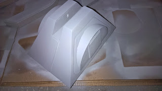


Saturday, April 18, 2015

Utility Arm Hybrid Part 2


More work on the mechanical Utility Arms

Had to order correct belts that would fit between the servo and the util arm itself.
I also added fittings and noticed that the clearance through the skin was too tight, I would have to sand/clear out the openings better to allow clearance of the arms.

Took the unit apart and ran some more holes to allow screwing through the outer plastic frame to the metal frame units.

Tested the unit against the arduino using some test code to run the servos with 


Here is a closeup of the gears connected and spacing between the arm and the outer box.


Completely assembled it was time to paint!


Taped off the main gear shafts (I actually couldn't pull them off so I left them on).


Primed the arms using a strong primer, waited 15mins - sprayed it again in the basement


Here is the other arm


The smells were so strong, the house smelled like primer paint... I was not the most liked person in the house for the next few days and took it out to the garage once warmer weather came (I needed 50 degrees or higher with low humidity).

Started the spray the R2 blue now... First coat... wait 15


Second Coat... wait 15.. then third.


Saturday, April 11, 2015

Sensor Work weekend

Running into issues with painting so moved back to the house and work on the sensor CPUs and connections.

Purchased 5 Arduino NANO sized CPUs which each will handle dedicated ping/sensor (distance detection) on each foot.

There will be 3 in the center foot and 2 in each outer foot.

The device is roughly 1.5 inches long and will need magnifying glass to solder the connectors to it.

Took the system out and connected the feet for testing the wiring between the 3 ping sensors (IR PING sensors) and the Arduino.

Then connected the arduino to the EZB robot CPU control system.


Here is a great shot of the EZB control CPU.. notice the white ribbon cable coming off the top.  It is actually the micro camera which will be located behind the EYE on the dome so it can do facial recognition etc.


The arduino is then connected to a screw down terminal shield adapter that allows me to quickly screw connect wires without permanently soldering them to the board.  Very nice.


Connecting each sensor requires 4 wires...
VCC (5v), GND and ECHO/TRIGGER.
The TRIGGER pins can be shared between all 3 as well as GND and 5V.


Taking the arduino nan out of the static bag... not much to look at.  I will connect the posts to the board and begin soldering them permanently to the board.  Once connected will run OSCILLOSCOPE meter tests on the power and such to verify that the pins are connecting correctly.


Here is a great shot of the size of the unit even inside the screw down terminal shield... very small.


Patience while soldering... my first unit was rough, as its been a year or so since I soldered my lights for the dome on R2 Version 1.0.

Getting older definitely as even looking through the magnifying glass was hard.


One at a time...


Steady as she goes...


There a completed piece, ready for the sensors to be permanently connected to the screw terminals.


Here is a great shot of the scale of the arduino and its pins.


There is 6 exposed pins on the top that have additional RX/TX pins and VCC/GND on them.


Well after much time it was a success... here is the schematic for anyone interested in how these will be wired into each foot.

Connectivity...
D18 on ezb tx to Rx on mini
D19 on ezb Rx to Tx on mini


UARTInit(0,2,9600)
sleep(1000)
UartWrite(0,2,"e")
sleep(1000)
$distance = UartReadavailible(0,2)
print ($distance)
this is a test script to use with the ezb