Thursday, December 24, 2015

R2 Upgraded to 24v for Christmas!

Going from 12v to 24v equals FAST!

I got the courage to serial the 2 batteries I have been using (they worked great during the release event in that each one gave me roughly 5 hours of run time while the other charged) and generate 24v to the 2 motor controllers on the R2 unit.

Foot Motor Controller: Dimension engineering Sabertooth 2 x 25 controller (2 x 25amp max)
Dome Motor Controller: Dimension engineering Syren 10a (1 x 10amp max)

The new connections now are:
  1. Serial 2 x 12v 18ah batteries connected to power distribution board
  2. a. Distribution board connects both the syren and sabertooth input to 24v now
    b. Distribution board connects to a 24/30v step down to 12v 10ah convertor
  3. 12v Convertor connects to the original 12v distribution board that powers everything else


Works perfectly!  he moves!

MERRY CHRISTMAS EVERYONE!

Wednesday, December 23, 2015

Drive Train Issues solved!

Dual Tensioner

Tensioner on the opposite side solved the issue of drive slippage...  due to "eyeing" it... its a little tight but solved the issue of slippage... I will do the second wheel a little looser and send back to Frank for design updates.


Bored a hole into the side of the drive mount and took a 1/4" - 20 X 1" machine screw and drilled a hole "eyeing it" offset from the main shaft hole on the opposite side. the above photo shows me drilling in the screw...


I took a left over 1/2" spacer that was leftover parts from the Razor Scooter pieces for the motor... it allows enough clearance between the outer wall and the wheel to protect the screw as the chain rubs against it.


Fitting the spacer onto the screw as I drive it into the frame... it pushes down the opposite side snug... should have gone a bit higher in placement, probably could have matched elevation of the drive hub.


Put the opposite side tensioner back in removing all access slack on the chain now.  The chain is very snug and pulls correctly both directions across the drive hub... no slippage VIOLA!


Top view showing the chain without any slippage as well as the screw completely in


Yes another view of the screw and the spacer inside the mount


Another view of the screw sit into the mount and space installed along with tensioner.  The chain is nice and slack free...


Sunday, December 20, 2015

Chain issues with drive train


Drive Train Issues

After using R2 for a full weekend event, there was tons of drive slippage
"The sound it makes similar to changing gears on a 10speed bike" and its horrendous...  Many times preventing R2 from moving forward correctly.

Once we got him home, removed the outer feet and disassembled the shells from the motor mounts.

Potential issues:
  1. There is maybe too much slop in the chain (although we cannot tighten it any more or move it any more on the links.
  2. The gears are loosing grip and letting the chain jump off the gear

I removed the retaining clip on the chain and tried to tighten, there is not enough slack to go another link.


Looking for answers


Friday, December 18, 2015

Baby's First day out: Broken HP and Dome Gear

The first time out for R2 exposed him to many challenges:
  • Children and adults all leaning on the dome when he is in automated mode (turning and making chirps randomly).
  • Weight when little hands press against the dome features such as the HPs

All this resulted in a very successful first day in the wild.
  1. The top dome HP fell into the dome due to some small child pushing it in.
  2. The dome gear tore off and snapped the screws due to fighting the weight of people when it wanted to turn :)

Bore out new holes through the gear into a new piece of plastic with the correct height.


The screws (4X40) were too long so I will cut them down once I add all the nuts.


Here they are cut down and ready to rock n roll!


All in all everything was fixable... no major issues, and...

The 12V 18amp Battery lasted roughly 5.5 hours and could have gone longer...


This is why we build R2s - I believe all the builders feel the same

When you see this all day long... watching children's eyes light up, smiles and hugs as well as feeling like R2 is really really alive is all worth it!


More to come from Day 2....

Thursday, December 17, 2015

Pre Release Visit to DESTINY USA


R2 made his first road trip to Destiny USA (Carousel Mall, Syracuse NY) and made a splash before the big event.

Baby's first day out


He will be there from Thursday till Friday night and then will be heading over to Shopping Town Mall on Saturday and Sunday for his whirl wind tour.

First Elevator Ride:

Then received some attention as we made our way down into the IMAX/RPX area where he will stay the evening till Release day.


Will post more as the event continues... stay tuned.

Wednesday, July 1, 2015

Wiring issues persist

Wiring for the weary hearted

Working with the design and putting it into code is one thing, but to actually connect it all and ensure it works is another.

Key things when we are wiring this system together:

  1. Keep the GND or ground common always between all devices
  2. Use the right gauge wire between the heaver loaded items (more amps = thicker gauge)
  3. Purchase a few spare knock off Arduino Mega - your gonna blow a few... trust me.  The magical fairy of blue smoke will come and visit you often.


Currently as of 7/1/2015 the design calls for

  • Arduino nano in each foot (nothing is in the center foot just due to lack of path to the foot shell from the body.
  • There is a cable that connects the nano A4 and A5 (SCL SDA or I2C) through the leg into the body and connecting to the SHADOW main controller or Arduino Mega or DUE,
Learn more about I2C here working with Arduinos:


Purchasing a DUPONT cable kit allowed me to create ends either MALE or FEMALE on each wire that ran from the body to the feet.


The kits run for $12 per and come with 1P - 6P connectors (housings) and both male as well as female ends.

You will need a proper crimper for these devices... you can purchase a good crimper for roughly $20 on ebay or amazon.


Currently because I am using a nano screw terminal sled connected to each nano I only needed to create connectors on one end of the long run from the foot to the body.

Because a majority of the connectors I will be interfacing with are MALE into the boards, I made the ends into FEMALEs.

I also needed a I2C hub of some fashion because of the amount of devices chattering across the lines.

Currently the device count is at 7 where the following is using I2C to communicate.
2 x Compass [Magtometers]
3 x arduino nano (PING Sensor units and PIR sensors)
1 x arduino mega (SHADOW main)
1 x arduino uno (EasyVR Voice recognition)
1 x marcduino (custom automation board for panel controls and sound)
1 x SD card reader unit
total: 10 items chatting....

Found these to be useful, low on stock I purchased 2 but only 1 arrived so far.

I2C Hub on Amazon


Saturday, May 23, 2015

Aluminum Dome PIE Panel installation

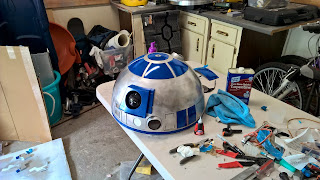
Began sanding and sanding and sanding


The dome is the most recognizable piece to R2 so very important to get it right the first time...


Very important to mark and number your panels with a number so you can easily re-match them to the correct area when gluing them back on or mounting them to the hinges.


Once marked I then removed all the inner panels from the dome using a small metal cutting saw.  This allowed me to make roughly 2 back and forth movements before cutting through the little tabs remaining that were connecting the panel to the shell.


What a mess... also note the outer dome is very sensitive to bending without the support of the inner dome. You will need to be very careful not to put too much force or lean on it while cutting.


Aluminum fragments... anything that had the residue left on it from the laser cutting was cleared off using the strong metal brush as seen below... this is very strong and sharp... cut myself many times.


Both pieces fit together very well and remove easy too...


Here is the lower dome pan as well as assembly pieces.  I have removed the dome gear from the frame so I can assemble it in the correct order.


Here are a few of the dome pie panel servo hinges...


Installing the hinge requires a few things...
You hand place the hinge inside and move it by hand each time testing clearance of the pie panel hinge back that it clears the opening.  This was tough as the hinge backing plate was almost cut to exact size... I ended up trimming down the lower edges to allow easy clearance.


Once in the correct placement, I quickly hot glued the assembly onto the dome inside and allowed it to cool.  This allowed me to work on getting all the hinges installed.  Once I got them all installed and in the correct placement, I drilled through from the inside out through the hinge to install #4x40 flat head screws to hold the hinges in place permanently.  

Since the outer dome covers the inner, it covers the screws as well.  To ensure flatness, I counter sinked the holes where the screw heads were to be installed outside in.


A great view of the hinges in place, you can see where I marked the holes connecting each of the hinges.


Once pie panel is not going to open at this time, this is due to money and I will configure it later.


Great shot of counter sink holes where the screws will be inserted.


I then install the screw and tighted down the bolt nut using a screw driver.


While I am in there I screwed through the inner dome to allow connecting the HP shells to the inner dome.


You can see where the inner shells are connecting through the screws and as I connect them down with the nuts, it holds the HPs inside securely.


Great view of all items connected and secured


Ran into some issues, as I was connecting the two domes together, I realized I hadnt cut the port for the camera to view out the radar eye!

Got out the saw and proceeded to almost cutoff my hand :)


Notice the oooops here where the saw kinda flung out... no prob, thank God that is behind the radar eye shell and quite hidden.


The PSI lens area I took 3" pipe, cut it and hot glued to the inner dome area


Purchased 3" 5mm thick lens material to work as a defuser for the lights that will be installed behind.


The upper HP that sits on the exposed pie panel didnt match or align with the holes.. I will hot glue this piece instead.


Started to install the panels against the hinges... note, I use painters tape and sit the pie panel against the hinge... I then flip the dome over and push the hinge against the pie panel and hot glue it temporarily in place...

I then installed the radar eye as well as lens I got from Guy Varden from the R2 builders group.


Here are the dome hinges all opening perfectly.