Tuesday, February 24, 2015

Center Vent Support

Center Vent Holder

Center vent area on the frame was nothing more than an open slot on the front of the frame.  Frank Pirz design probably relies on the outer skin to hold the pieces in place.  Since I am working on a more mechanical version of this R2 unit... I wanted to start building these inserts to support the pieces so I can add/remove them as needed.


Above you can see where the slot opening is where the vents would sit... the below illustration shows where they would be placed on the R2 unit.


Since this would require some sort of insert, I got to work on a box kit that fit tightly into the R2 center slot opening where the vents would be.

I measures the rounds and depth of the inserts on the frame and then proceeded to cut out my pieces.  I will use 2 tiers,,, one each to hold the vent opening.


Once you drew the lines, a few scores with the exacto knife over the same spot, you can then snap the plastic piece perfectly.


The tracing of the insides and shape of the opening on the frame...These rounds will be more difficult to cut since I didn't have my router setup.


Not bad... I cut them out by hand using the first piece and then tracing the knife along the edges.


Using Weld-on 16 I was able to connect the pieces with enough time to adjust before the glue hardened


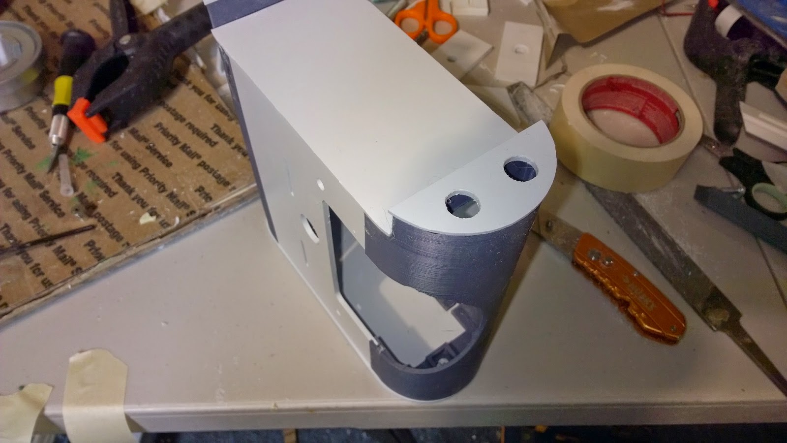
Here is the final piece... ready for insert.


Fits snug and perfectly!  I will add a center vent to test as well...


Perfect, ok now to apply the skins to see where the placement of the vent holes are in relation to the skin/frame.

NOTE: will need to do the same for the mechanical arms on the front as well.


Sunday, February 22, 2015

Battery Boxes

For the love of Pete... lots of mistakes

I started on the battery boxes in between work on the center foot.  During which I ran into some major issues which we will cover in the blog.


The pieces included some 3D printed ends and parts from Frank (this was similar to the skirt pieces for the center and outer foot shells... his plastic is very strong.. although we shall see soon not strong enough as we thought.


Dry fitting it all together took some time... the pieces sort of fit together but needed lots of sanding in the seem areas where the pieces go inside themselves.


Used 150 grit paper and sanded... sanded... sanded till I could move the pieces freely in and out of the slots.  Very sour arms, hands.. tired.


Dry fitting looks ok.. I see where I will need to definitely file and sand a lot.


More sanding, more sanding... This edge and the below shot is the outer cavity where there is a door that I will assembly that allows me to expose the internal parts so we can screw this piece to the inside of the foot (outer foot) shell.


Another view of the slot and how the pieces slide into the slots.


And another shot.... lots of sanding...


Here I am trying to test slide the door piece I made in and out of the shell... it is very difficult so I will continue sanding.


Doesn't quite slide nicely...


I test connected the battery box to the foot shell and screwed it in place... I can use the battery boxes to hold the mini arduino and sensor wires that will run into the foot for distance tracking and such.


Another view of the battery box attached to the foot shell.


Note, the sliding panel will be connected with 3/8" flat screws into bolts that are inside super-glued into holders.  


There is a glued in place nut that the screw connects to inside the plastic 3D printed part.


I couldn't unscrew one of the bolts... something is wrong.


Oh crap... the superglue leaked into the nut and froze the screw and nut together.  This is not looking good...

NOTE: After a few hours.... matters turned worse... I ended up having to crack the battery box... then took some vice grips and proceeded to saw off the end of the screw so I can remove it.  After 30 minutes the screw was cut and now I had to repair the battery box.


Back on track, after gluing the pieces that are static... I used weld-on 16 again.. slow drying but glue substance.


The filing is coming along.. looks great.  I will need to sand, file, sand over and over several times before I move onto the next area.


Notice the end caps will need lots of filing... I ended up using the hobby knife and cutting the excess plastic closer to the lip so I didn't have to file so much.  Very careful not to cut too close.


Another view of the end cap where the threaded spacers and cables will come out of... this cap will need to be filed down too.


Much better... this is what it looks like completely filed and sanded down.


Here are the two battery boxes with the end caps completed.


Here are the 2 battery boxes completed.


Center Foot Time

Center feet - cheap labor

Awesome sauce! 
Received the center foot pieces via mail from Frank Pirz


Was going to wait on this till next weekend but had some little visitors for the past 2 weeks that asked and asked to help with R2. 


I said sure why not and they proceeded to help:
  • Sanding/Filing - Josh Phipps
  • Cutting and trimming pieces - Zachary Phipps
These two pushed me to get the pieces tied together and assembled

Here is Zach working on trimming... he looks excited!


SO we started to assemble the frame of the center foot, this is key to holding the weight of R2 when he is moving forward etc... so we are going to use weld-on 16 which takes longer to dry and is more like glue in texture.  Weld-on 4 is like water which is what most of the work was done last time with.


We seperated all the parts out, checked off each part... ran into some issues with mismatched parts, looks like Frank has changed his design and didnt update the documentation as yet.  we will work through it when we get to those parts.

First we dry fitted everything together and made sure we understood the assembly of the frame.
Looks good.


Next we simply glue each piece together of the frame, connecting it all to the bottom plate with has a 4" radius hole at the bottom to handle the caster.


Next we dry fitted the center ankle to the foot to ensure that the width of the channel was correct.


Looks good.


Frame is complete... now to move onto the outer shell.


Taping the shells together at the bevel allows me to stand it up in place and pour the glue into the seams to better the connection to each plate.


Ok now to glue it...


ok looks dry - again weld-on 16 dries very slowly... so I will come back to the shell in a hour or so.


We will use the green putty (


While I was at it... I filled in the old shell too, oh boy green everywhere.


Now they are ready to assemble


I placed the outer shell over the frame and glued it into place... verified that all the surfaces were touching.


I then added the magnets to slots on the sides (these will be used to join the outer shell doors without having to glue and allow easy removal in the future to get to the inner parts.

NOTE: I used supermagnets from homedepot... they work great!

I flipped over the center foot and added green putty (bondo) around the edges between the shell and the bottom plate.  This allowed me to have a good surface to glue the bottom skirt to.


The putty is called Squadron Green putty... model airplane builders generally use this stuff to fill in the edges on planes etc.  This stuff is expensive as its only a 5ounce tube and it took almost the entire tube for just the bottom of the foot.
You can find this stuff on ebay or at any local hobby shops...

http://www.ebay.com/itm/like/331456389101?lpid=82&chn=ps

 I then sanded and filed the surface of it down so it was even and flat all around. 


Adding the front and rear slits and top channel skin and presto... we are ready to add the skirt.


This part took some time, I had to use weld-on 16 again and let it sit then moved the pieces together tight as the glue gets more sticky the longer it sits.


Nice fit on the edges.... its like assembling a picture frame


There it is!  Completed in 5-6 hours tops... nice job Frank


Here is another picture of the foot connected to the center ankle.